
Specifications
Building
Standard for application
Stainless steel pipes is made of STS 304/316K15A-100A).
Over 80A is possible to use Sch5(KS D 3576)
Scope of application
Piping for water apply, potable water and hot water, water heating and cooling, Firefighting.
Material
STS 304, 316L
Installation
1. Cut pipe
Cut a pipe at right angles to its axis. See photos 1 -1,1 -2.
Cut a pipe at right angles to its axis. See photos 1 -1,1 -2.
2. Deburr the end of pipe
As burrs is able to cause leakage and corrosion, Burrs sticking on the pipe-end must be removed.
See, notice 1.2 and photo 3-1,3-2
As burrs is able to cause leakage and corrosion, Burrs sticking on the pipe-end must be removed.
See, notice 1.2 and photo 3-1,3-2
3. Mark insertion depth
To secure the required insertion depth, mark on the pipe by using permanent pen
To secure the required insertion depth, mark on the pipe by using permanent pen
4. Assemble the pipe tube and fitting
Insert the pipe into the joint as much as insertion depth with rotating slightly and pushing in an axial direction.
See, notice 3 and 4-1,4-2
Insert the pipe into the joint as much as insertion depth with rotating slightly and pushing in an axial direction.
See, notice 3 and 4-1,4-2
5. Press the fitting and tube with exclusive tool
Place press tool at a right angle over fitting bead. Stat the pressing process.
See, notice 4 and 5
– Gun Type G2 Tool (15A-50A) See, photo 5-1 -a, 5-1 -b
– Gun Type F Tool (65A-100A) See photo 5-2-a, 5-2-b
Place press tool at a right angle over fitting bead. Stat the pressing process.
See, notice 4 and 5
– Gun Type G2 Tool (15A-50A) See, photo 5-1 -a, 5-1 -b
– Gun Type F Tool (65A-100A) See photo 5-2-a, 5-2-b
6. Remove the protective film after pressing
Easily removed after pressing.
See, photos 6-1,6-2
Easily removed after pressing.
See, photos 6-1,6-2
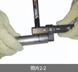
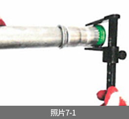
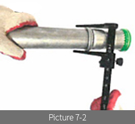
7. Check the dimension after pressing
Use the vernier calipers or the zig to check whether the pressing is good or not. See 4 and 5 in the notice.
See photo 7-1 for the normal pressing (press)/ See, photo 7-2 for the abnormal pressing (no-pass)
Use the vernier calipers or the zig to check whether the pressing is good or not. See 4 and 5 in the notice.
See photo 7-1 for the normal pressing (press)/ See, photo 7-2 for the abnormal pressing (no-pass)
Inspection and Testing
Inspection
Inspect whether the pressing is formed in a shape of circle and showing the double circle-shaped groovedistinctively. If not sufficient, check with vernier calipers or jigs
Inspect whether the pressing is formed in a shape of circle and showing the double circle-shaped groovedistinctively. If not sufficient, check with vernier calipers or jigs
Testing
• After all connections have been pressed, test with water or air at 3-‘3times haiger than working pressure when testing with air. use the soap bubble to check
• When Pressure testing, the tap water should be used principally. If not supplied, use the purified water to prevent the corrosion.
• Drain out the water completely after testing in order to prevent corrosion by accumulated foreign matters.
Notice
➀If it is inevitable to use a saw or an abrasive cut-off machine when cutting the pipe, remove the burr carefully
on the inside and outside using a file or a grinder in order to prevent damageto the rubber ring
➁ Keep the AB-JOINT at as dean a place as possible. Clean out the pipe-ends before inserting it into the AB-JOINT
➂ When inserting AB-JOINT into the pipe, keep them in a straight line and insert so as not to damage to the rubber ring.
If it is not inserted smoothly, apply the water over the rubber ring within the AB-JOINT
➃ Correctly place the press tool jaw with the groove of two over the curling of joint at a 90° angle and then press the joint
➄ Remove the protective film after the pressing to distinguish definitely “pressed or not”
➅ Be sure to inspect whether the pressed shape is normal or abnormal.
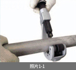
Rotary cutter
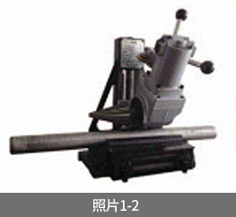
Electric cutter exclusively for AB-JOINT
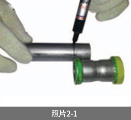
Insertion depth marking
Insertion depth marking for AB-JOINT
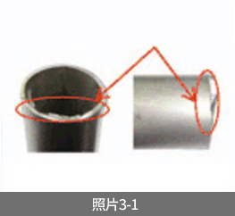
Before deburring
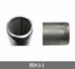
After deburring
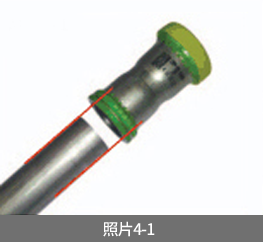
Before the pipe insertion
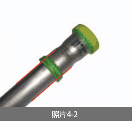
After the pipe insertion
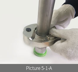
Bead fo the fittin is inserted intro the groove of hte press jaw(G2 Tool)
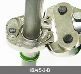
Under pressing(G2 Tool)
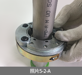
JBead of the fitting is inserted into the groove of the press jaw(F Tool)
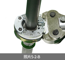
Under Pressing(F Tool)
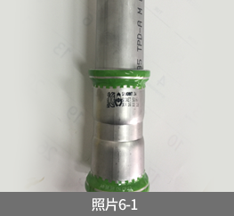
Before removing the crimping film
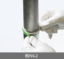
After removing the crimping film
Abnormal Pressing(Non-pass)
Normal Pressing(Pass)
SR-JOINT Notice
– Use both the pipe cutter and press tool exclusively
for AB-JOINT
– Deburr after pipe cutting definitely to prevent the damage of sealing ring and corrosion
– Insert after the insertion depth marking on the pipe
– Check after the pressing whether completely pressed or not
– Using measuring tool and then move to the next spot (Remove the crimping film prior to the check)
– Maintain the press tool thoroughly so as not to rust inhibitors
– Jaw and collar should be cleaned using anti-rust and corrosion
– Be careful of welding around the press-joint putthe protective cover over the pipe not to cause anydamage to the rubber ring by the flame and welding slag
Table of Dimension after Pressing (SCH5)
| Normal Size | Average OD | Joint OD before pressing | Joint OD after pressing | Tolerance |
| 13SU | 15.88 | 23 | 21.2 | ±0.3 |
| 20SU | 22.22 | 30.5 | 28.3 | |
| 25SU | 28.58 | 37.2 | 34.5 | |
| 30SU | 34 | 45 | 41.9 | |
| 40SU | 42.7 | 55.7 | 51.9 | ±0.4 |
| 50SU | 48.6 | 62.2 | 57.1 | |
| 60SU | 60.5 | 76.5 | 70.7 | |
| 75SU | 76.3 | 95.6 | 88.6 | |
| 80SU | 89.1 | 111.2 | 103.8 | ±0.5 |
| 100SU | 114.3 | 137.3 | 128.5 |
Insertion Depth by Sizes
| Normal Size | 13SU | 20SU | 25SU | 30SU | 40SU | 50SU | 60SU | 75SU | 80SU | 100SU |
| Insertion Depth | 22.8 | 25.1 | 25.1 | 35 | 36 | 44 | 49 | 73 | 78 | 79 |