Specifications
DRP-JOINT
Material
AB, SM, DP-JOINT : Stainless steel pipes for fitting, KS D 3576 and KS D 3595
CN-JOINT : Seamless copper and copper alloy pipes, KSD 5301
CP-JOINT: Seamless copper and copper alloy pipes, KS D 5301
CS-JOINT : Carbon steel pipes for fitting , KSD 3507
Scope of application
Piping for shipbuilding, water apply, potable water and hot water, water heating and cooling, Firefighting
Installation
1. Cut pipe
Cut a tube at right angles to its axis. See the Pic. 1-1,1-2
Cut a tube at right angles to its axis. See the Pic. 1-1,1-2
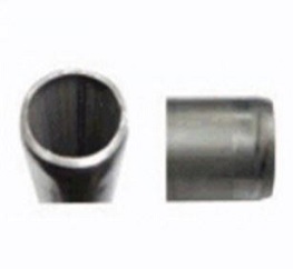
2. Deburr the end of pipe
As burrs might cause leakage and corrosion, Burrs sticking on the pipe-end must be removed.
See, notice ➀ and Pic. 3-1,3-2
As burrs might cause leakage and corrosion, Burrs sticking on the pipe-end must be removed.
See, notice ➀ and Pic. 3-1,3-2
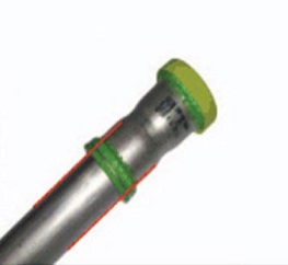
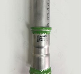
3. Mark insertion depth
To secure the required insertion depth, mark on the pipe by using permanent marker.
To secure the required insertion depth, mark on the pipe by using permanent marker.
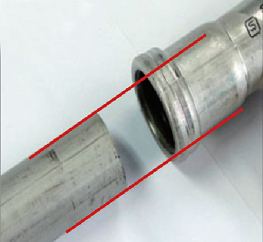
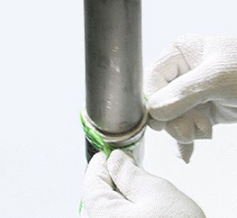
4. Assemble the pipe tube and fitting
Insert pipe into fitting as required insertion depth by rotating slightly and pushing in an axial direction.
See, notice ➂ and 4-1,4-2
Insert pipe into fitting as required insertion depth by rotating slightly and pushing in an axial direction.
See, notice ➂ and 4-1,4-2
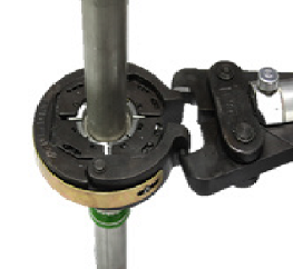
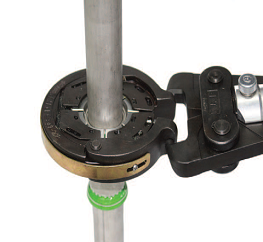
5. Press the fitting and tube with exclusive tool
Place press tool at a right angle over fitting bead. Start the pressing process.
See, notice ➃ and ➄
– With G2 typed jaw (15A-50A) See, Pic. 5-1 -A, 5-1 -B
– With F typed jaw (65A-100A) See Pic. 5-2-A, 5-2-B
Place press tool at a right angle over fitting bead. Start the pressing process.
See, notice ➃ and ➄
– With G2 typed jaw (15A-50A) See, Pic. 5-1 -A, 5-1 -B
– With F typed jaw (65A-100A) See Pic. 5-2-A, 5-2-B
6. Removing the film after press
Remove the film after installation
(It is easy to remove after press) See the Pic. 6-1,6-2
Remove the film after installation
(It is easy to remove after press) See the Pic. 6-1,6-2
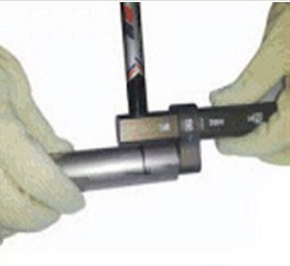
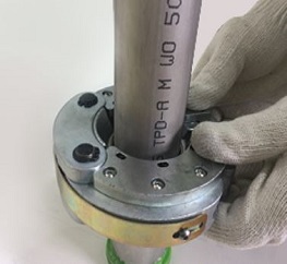
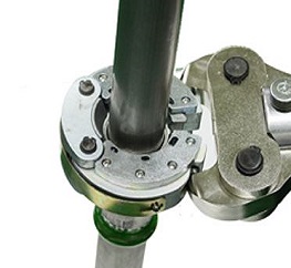
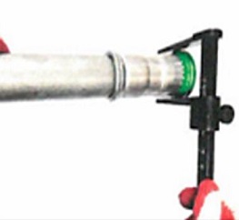
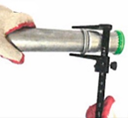
7. Checking the dimension after pressing
Using the vernier calipers or the zig for inspection to check whether the pressing is properly worked or not.
See Pic. 7-1 for the normal press result(passed)/See the Pic. 7-2 for the abnormal press result (failed)
Using the vernier calipers or the zig for inspection to check whether the pressing is properly worked or not.
See Pic. 7-1 for the normal press result(passed)/See the Pic. 7-2 for the abnormal press result (failed)
Inspection
Inspection
Using the naked eye to inspect whether the pressing is formed in a shape of circle and whether a double circle-shaped groove appears: if not sufficient, using the jig for inspection to inspect
Using the naked eye to inspect whether the pressing is formed in a shape of circle and whether a double circle-shaped groove appears: if not sufficient, using the jig for inspection to inspect
Notice
➀ If it is inevitable to use a saw or an abrasive cut-off machine when cutting the pipe, reducing the cut area in order to prevent damage to the rubber ring or using a grinder to remove the burr
➁ Keeping the DRP-JOINT at as clean a place as possible; keeping the opening clean before inserting the pipe into the DRP-JOINT
➂ Paralleling the DRP-JOINT with the pipe before inserting the pipe so as not to damage the rubber ring; applying liquids like water over the rubber ring within the DRP-JOINT in order to insert the pipe smoothly
➃ Correctly adjusting the bead of the DRP-JOINT to the groove of the clamp and then pressing so that the pipe may be right-angle against the clamp
➄ Removing the film after pressing so that it may be possible to distinguish between before and after pressing
➅ Using the naked eye to inspect whether the pressed area is evenly pressed in a shape of circle or using a jig for inspection
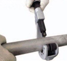
Picture 1-1. Rotary cutter
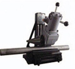
Picture 1-2. Exclusive electric cutter
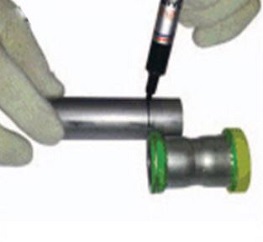
Picture 2-1. Marking insertion depth 1.
Picture 2-2. Marking insert depth 2.

Picture 3-1. Before deburring
PIcture 3-2. After deburring
Picture 4-1. Before the pipe insertion
Picture 4-2. After the pipe insertion
Picture 5-1-A. Assemble a jaw (G2 Type)
Picture 5-1-B. press (G2 type tool)
Picture 5-2-A. Assemble a Jaw (F Type)
Picture 5-2-B. Press (F TypeTool)
Picture 6-1. Before removing the film
Picture 6-2.removing the film
Picture 7-1. Abnormal Pressing(Non-pass)
Picture 7-2. Normal Pressing(Pass)
Length of the insert depth by pipe diameter
AB-JOINT
| Pipe diameter | 15A | 20A | 25A | 32A | 40A | 50A | 65A | 80A | 100A |
| Minimum Insert Depth (mm) | 25.0 | 25.0 | 35.0 | 35.0 | 43.0 | 50.0 | 70.0 | 75.0 | 75.0 |
DP-JOINT
| Pipe diameter | 15A | 20A | 25A | 32A | 40A | 50A | 65A | 80A | 100A |
|
Minimum Insert Depth (mm) |
25.0 | 25.0 | 35.0 | 35.0 | 43.0 | 50.0 | 70.0 | 75.0 | 75.0 |
SM-JOINT
| Pipe diameter | 15A | 20A | 25A | 32A | 40A | 50A | 65A | 80A | 100A |
|
Minimum Insert Depth (mm) |
19.9 | 19.9 | 27.4 | 28.1 | 34.0 | 38.6 | 55.8 | 61.4 | 62.1 |
CP-JOINT
| Pipe diameter | 15A | 20A | 25A | 32A | 40A | 50A | 65A | 80A | 100A |
|
Minimum Insert Depth (mm) |
21.0 | 22.1 | 28.1 | 32.3 | 34.5 | 37.5 | 54.0 | 60.0 | 61.1 |
CN-JOINT
| Pipe diameter | 15A | 20A | 25A | 32A | 40A | 50A | 65A | 80A | 100A |
| Minimum Insert Depth (mm) | 18.8 | 18.8 | 19.0 | 22.5 | 26.3 | 26.3 | 45.0 | 45.0 | 45.0 |
DRP-JOINT Notice
-Check press tool daily base
(After using, brush to remove foreign substance and prevent rusting)
-Deburr tube Inner Diameter/Outer Diameter by using exclusive cutter
(Prevent from rubber ring to be damaged and rusted)
-Insert pipe after marking insert depth line
-Check with Jig to confirm the after press condition
-In case of any press failure, stop the working process and check tool